
 Business License

Powder Coating Line Layout: A Complete Engineering Guide for Your Factory
Marcus Chen spent six months negotiating with three separate vendors for his new powder coating production line. The spray booth arrived from one supplier, the curing oven from another, and the pretreatment system from a third. When his installation team finally tried to connect everything, they discovered the curing oven exhaust duct would collide with the overhead conveyor return rail. The line sat idle for three weeks while engineers redesigned the ductwork.
Marcus learned an expensive lesson: a powder coating line layout is not an afterthought. It is the foundation that determines whether your line runs at capacity or bleeds money through bottlenecks, rework, and downtime.
If you are planning a new coating facility or expanding an existing one, you already know the stakes. The layout affects throughput, coating quality, energy consumption, and operator safety. In this guide, you will learn how to design a powder coating line layout that aligns each stage of the process with your factory footprint, workpiece specifications, and production targets. We will cover the five essential stages, conveyor integration, energy infrastructure, and the mistakes that even experienced engineers make.
What Is a Powder Coating Line Layout?
A powder coating line layout is the spatial and process arrangement of all equipment, material flows, and utility connections required to move workpieces from raw metal through pretreatment, powder application, curing, and final inspection. A complete layout includes floor plans, elevation drawings, conveyor routing, utility drops for electricity and gas, exhaust routing, and operator access pathways.
Unlike a simple equipment list, the layout determines how workpieces travel through each stage without backtracking, how operators interact with the system during loading and unloading, and how maintenance crews access critical components. It also defines the relationship between the coating line and upstream fabrication processes, such as stamping or welding, as well as downstream packing and shipping.
Deqing Leixin approaches every powder coating line layout as a turnkey engineering exercise. Our project team evaluates your workpiece dimensions, weight, daily output target, available factory dimensions, and heating preferences before producing detailed layout drawings. This ensures that the pretreatment tanks, spray booth, curing oven, and conveying system operate as an integrated production system rather than a collection of disconnected machines.
Want to see how a layout drawing looks for your workpieces? Explore our coating line design guide and submit your specifications for a free preliminary layout proposal.
The Five Essential Stages of Every Powder Coating Line Layout
Every automatic powder coating line follows a logical sequence. The layout must preserve this sequence while minimizing travel distance, eliminating cross-traffic, and providing safe operator access.
Stage 1: Loading and Incoming Workpiece Buffer
Workpieces enter the line at a dedicated loading zone. This area needs sufficient space for raw parts staging, fixture or hanging rack preparation, and quality pre-checks. Layout planners often underestimate the buffer zone, which leads to congestion at shift changes and production peaks.
A well-designed loading zone includes:
A 2 to 4-hour workpiece buffer based on peak daily output
Clear floor markings separating raw material from coated finished goods
Overhead crane or forklift access for heavy workpieces
Proximity to upstream fabrication to minimize internal transport distance
Stage 2: Surface Pretreatment System
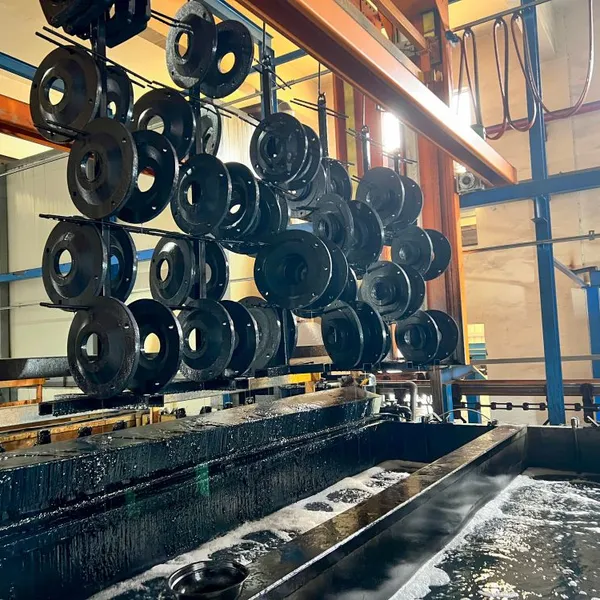
The pretreatment stage is where coating adhesion is won or lost. In a typical powder coating line layout, the pretreatment system occupies a straight-line section with workpieces immersed or sprayed through sequential chemical stages. Common configurations include degreasing, water rinse, phosphating or conversion coating, a second rinse, and a demineralized water final rinse.
Layout considerations for pretreatment include:
Tank dimensions must accommodate the largest workpiece plus handling fixture
Chemical supply and wastewater collection require floor drainage and containment
Drying stage, whether by hot air knife or evaporation tunnel, needs space before the spray booth
Operator access for chemical testing and tank maintenance
Our surface pretreatment system configurations use 304 stainless steel tanks with automatic water blowing systems to remove residual moisture before coating application. Proper layout placement prevents water carryover into the powder spray zone, which causes film defects and adhesion failures.
Stage 3: Powder Spray Application and Recovery
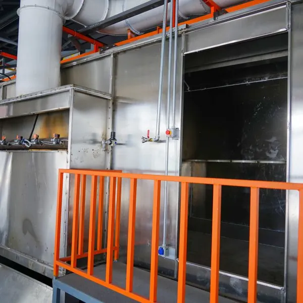
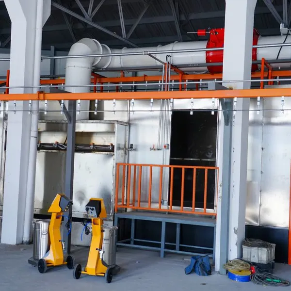
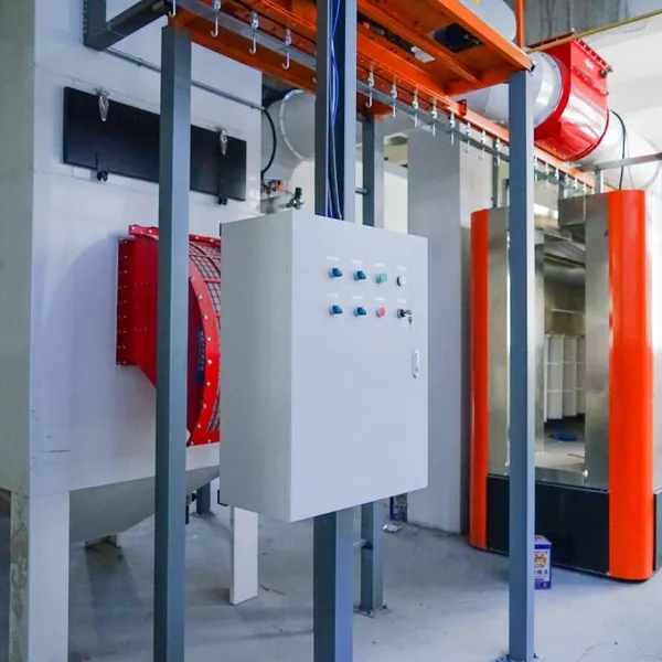
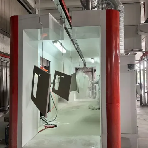
The spray booth is the visual and operational heart of the powder coating line layout. Automatic powder spray booths with cyclone recovery systems require controlled airflow, precise gun positioning, and efficient overspray reclamation. The booth must connect seamlessly to the conveying system while providing maintenance access to reciprocators, powder hoppers, and filter cartridges.
Key layout parameters for the spray zone include:
Booth dimensions based on maximum workpiece envelope plus 300 to 500 mm spray clearance
Cyclone recovery unit placement to minimize duct length and pressure loss
Powder feed room or sieving station adjacent to the booth for material conditioning
Operator viewing windows and manual touch-up stations for complex geometries
The servo reciprocating machine, with spraying heights up to 2,500 mm and configurable gun counts, must be positioned so its stroke pattern covers the full workpiece cross-section without interference from conveyor rails or support structures.
Stage 4: Curing Oven
After powder application, workpieces enter the curing oven where the powder melts, flows, and cross-links into a durable polymer film. The curing oven in a powder coating production line layout typically uses a tunnel-type configuration with a bridge-style entry and exit to prevent heat loss and contamination.
Layout planning for the curing stage must address:
Oven length based on required cure time at line speed, usually 10 to 20 minutes at 180 to 200 degrees Celsius
Thermal energy source placement, whether gas-fired burners, electric heating elements, or steam heat exchangers
Exhaust stack routing that complies with local emission standards and avoids interference with building structures
Cooling zone after the oven exit to bring workpieces to handling temperature
Deqing Leixin curing ovens offer thermal energy options from 300,000 to 1,000,000 kcal with precision temperature control within plus or minus 3 degrees Celsius. The layout must allow adequate clearance around the oven shell for insulation access and burner maintenance.
Stage 5: Unloading and Final Inspection
The unloading zone mirrors the loading area in spatial requirements. Operators remove cured workpieces, perform visual and thickness inspection, and transfer accepted parts to packing or assembly. The unloading zone should be physically separated from raw material staging to prevent mix-ups.
A complete powder coating line layout includes space for:
Film thickness measurement and adhesion testing stations
Rework rack for parts requiring touch-up or recoat
Finished goods quarantine area pending quality release
Packing material storage adjacent to the unloading station
Factory Space, Workflow, and Material Flow Planning
Elena Kowalski, a production engineer at a hardware manufacturer near Krakow, inherited a powder coating line that had been installed in a converted warehouse with irregular column spacing. She measured every bottleneck and discovered that the conveying system made a 90-degree turn immediately after the spray booth, causing uneven powder distribution on the trailing edges of larger panels. By relocating the booth 4 meters and re-routing the conveyor to a gentle curve, she cut rework rates by 18% and increased effective throughput without changing the conveyor speed.
Elena's experience illustrates why factory space analysis must precede equipment selection. Before committing to a powder coating line layout, gather the following data:
Factory dimensions: Length, width, and clear height including column locations, crane rails, and existing utility trenches
Floor load capacity: Pretreatment tanks filled with chemical solution can exceed 5,000 kg per square meter
Door and dock locations: Raw material entry and finished goods exit should flow in one direction when possible
Expansion buffer: Reserve 15 to 20% additional linear space for future capacity increases or additional spray booths
The ideal material flow follows a straight line or a U-shape. Straight-line layouts minimize conveyor length and are easiest to automate. U-shaped layouts consolidate loading and unloading at the same end of the factory, which can reduce operator travel but requires careful routing to prevent cross-contamination between raw and finished workpieces.
Conveyor System Selection and Layout Integration
The conveying system is the circulatory system of your powder coating production line. It connects every stage and dictates the cycle time, workpiece spacing, and line flexibility. Common conveyor types for powder coating include overhead power-and-free systems, enclosed track conveyors, and skid-based ground conveyors.
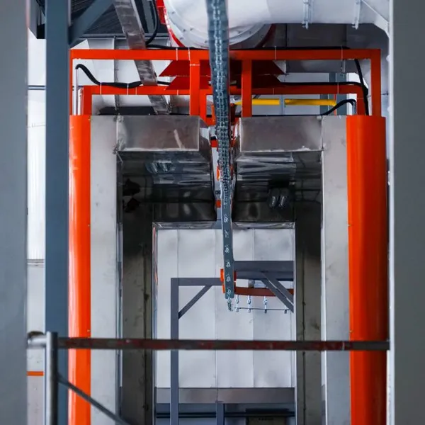
Overhead suspension conveyor chains are the most common choice for automatic powder coating lines because they keep workpieces clear of floor equipment, simplify pretreatment dipping, and allow dense loading in the curing oven. Layout integration requires:
Chain pitch and hanger spacing matched to workpiece size and oven density limits
Elevation changes to accommodate pretreatment tank depths and spray booth working heights
Drive and tension stations positioned for maintenance access without disrupting production
Horizontal turns with minimum radii to prevent workpiece swing and collision
Power-and-free systems add buffer capacity by allowing individual workpiece carriers to stop or accumulate independently of the main chain. This is valuable when coating mixed workpiece sizes or when upstream fabrication delivers parts irregularly. The layout must include buffer zones before and after the spray booth to decouple pretreatment and curing from the application stage.
When designing your powder coating line layout, always verify that the conveyor path provides adequate clearance around building columns, overhead lighting, and fire suppression systems. Our overhead conveyor system designs include chain auto-refueling systems and emergency stop circuits integrated into the line control architecture.
Energy Infrastructure and Utility Placement
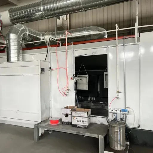
A powder coating line layout is also an energy map. The pretreatment system needs electricity for pumps and blowers. The spray booth needs compressed air for fluidization and gun operation.
The curing oven is typically the largest energy consumer, whether heated by natural gas, diesel, electricity, or steam. The control system needs clean electrical supply with proper grounding for electrostatic safety.
Utility placement should follow three principles:
Cluster high-demand utilities: Gas mains, electrical substations, and compressed air headers should be positioned to minimize distribution length to the curing oven and spray booth
Isolate chemical services: Pretreatment chemical supply and wastewater lines should run in dedicated trenches or overhead racks, separated from electrical conduits
Plan for redundancy: Critical utilities such as oven combustion air and booth extraction fans should have backup power or alarm systems to prevent coating loss during outages
Heating source selection has a major impact on layout. Gas-fired curing ovens need proximity to fuel supply lines, proper ventilation for combustion air, and flame safeguard equipment. Electric ovens require substantial transformer capacity and cable routing but eliminate fuel storage and combustion exhaust considerations. Steam-heated ovens need boiler proximity and condensate return lines.
Ready to evaluate which heating technology fits your infrastructure? Review our gas vs electric curing oven comparison to understand the operational cost and layout implications of each option.
Common Layout Mistakes That Drain Efficiency
Even experienced facilities managers make layout decisions that constrain performance for years. Here are the most costly mistakes we encounter when reviewing existing powder coating line layouts:
Insufficient clearance for maintenance. Spray booth filters, cyclone separators, and oven burners require regular access. If the layout packs equipment against walls or columns, routine maintenance becomes a production shutdown. Always provide a minimum 1-meter maintenance aisle on both sides of major equipment.
Ignoring thermal expansion and vibration. Curing ovens expand when heated and transmit vibration to adjacent structures. Layouts that rigidly connect the oven to the spray booth or building steel can cause misalignment of conveyor paths and ductwork leaks.
Poor exhaust and makeup air routing. Spray booths need balanced extraction and fresh air supply. Layouts that place makeup air intakes near oven exhaust stacks create thermal short circuits. Exhaust ducts that run through unconditioned spaces can condense and drip into the booth.
Neglecting operator ergonomics. Loading and unloading stations positioned too high or too low cause fatigue and handling damage. Workpiece hanging points should be between 0.8 and 1.2 meters from the floor for manual loading, or matched to automated loader height if robotics are planned.
Failing to plan for quality checkpoints. Without designated inspection stations in the layout, operators tend to check quality at the unloading area, which creates congestion and delays. Include intermediate inspection points after pretreatment drying and after curing.
Conclusion
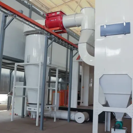
A well-executed powder coating line layout transforms individual machines into a coherent production system. It ensures that workpieces flow smoothly from loading through pretreatment, spray application, curing, and inspection without backtracking, bottlenecks, or cross-traffic. It provides operators with safe, ergonomic access to every stage. It positions utilities for efficient energy distribution and straightforward maintenance.
The team at a mid-sized furniture manufacturer in Vietnam learned this when they worked with Deqing Leixin to redesign their existing line. By relocating the pretreatment system 6 meters, adding a power-and-free buffer before the spray booth, and switching from a batch oven to a tunnel-type curing oven, they increased daily throughput by 34% and reduced energy consumption per part by 22%. The investment in professional layout engineering paid for itself in under 14 months.
Whether you are building a new facility or upgrading an existing powder coating production line, start with the layout. Define your workpiece envelope, daily output target, and factory constraints first. Then select and position equipment to match that plan, not the other way around.
Submit your workpiece dimensions, maximum daily output, and available factory space. Our engineering team will prepare a preliminary layout and quotation within three business days. Every line we design is custom-engineered to your specifications, from pretreatment configuration through conveyor routing and curing oven integration.
Recently Posted
-
Conveyor Speed Calculation for Coating Lines: A Complete Guide
June 26, 2026Last March, a hardware manufacturer in Ningbo raised the chain speed on its powder coating line by 15% to clear a backlog. Three d Read More
 -
Conveyor Line Design: A Complete Engineering Guide for Coating Lines
June 26, 2026Last autumn, a hardware manufacturer in Vietnam commissioned a new powder coating line. The pretreatment tunnel, cyclone-recovery Read More
 -
Overhead Conveyor System: Engineering Guide for Coating Lines
June 26, 2026Last autumn, a hardware manufacturer in Ningbo faced a familiar problem. Their new powder coating line had to fit inside a buildin Read More
 -
Industrial Paint Booth: A Complete Engineering Guide for Manufacturers
June 26, 2026When Mike Chen expanded his metal furniture factory in Zhejiang Province last spring, he assumed the new spray area would solve hi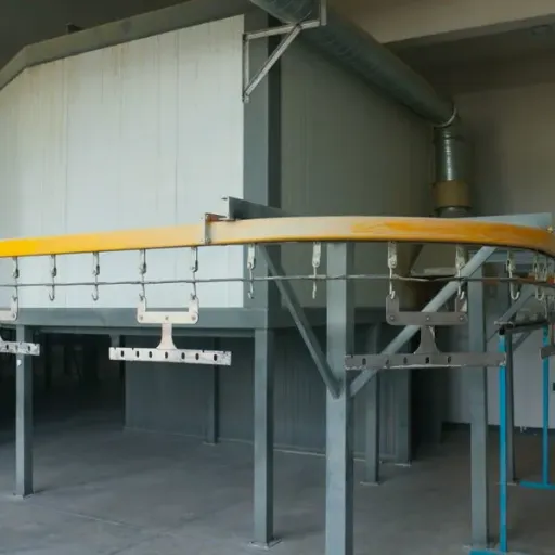 Read More

Contact Us
Recommended Products
-
 Industrial Custom Spray Coating Line for Hardware Anti‑Corrosion TreatmentNegotiableMOQ: 1 Set
 -
Industrial Electrophoresis Line for Metal Water Pump Workpieces ProcessingNegotiableMOQ: 1 Set
-
Custom E‑Coating Production Line for Water Pump Parts Surface FinishingNegotiableMOQ: 1 Set
-
China OEM Custom E-Coating Machine and Cathodic Electrophoresis Production LineNegotiableMOQ: 1 Set
-
Industrial Electrophoretic Coating Line With Custom Design for Metal WorkpiecesNegotiableMOQ: 1 Set
-
Intelligent Automated Electrophoretic Coating Line for Powder Coating Production EquipmentNegotiableMOQ: 1 Set
-
Full Automatic Custom Electrophoretic Coating Line for Industrial Metal ComponentsNegotiableMOQ: 1 Set
-
Heavy‑Duty Continuous Powder Coating Line for Big Cabinet Anti‑Corrosion FinishingNegotiableMOQ: 1 Set
-
Energy‑Saving Powder Coating Line for Large Industrial Cabinet Surface ProtectionNegotiableMOQ: 1 Set
-
Environmental Friendly Powder Coating Line With High Recovery for Large CabinetsNegotiableMOQ: 1 Set
-
Large Manual Industrial Curing Oven for Metal Powder Coating MachineryNegotiableMOQ: 1 Set
-
Industrial Plastic Drying Oven With PLC Control and 304 Stainless Steel HopperNegotiableMOQ: 1 Set
-
High Efficiency Plastic Raw Material Dryer for Plastic ProcessingNegotiableMOQ: 1 Set
-
Compact E-Coating System for Small Metal Components in Automotive & Medical Device ProductionNegotiableMOQ: 1 Piece
-
Gantry Transport Type Electrophoretic Coating Line for Industrial WorkpiecesNegotiableMOQ: 1 Set
-
Custom Gantry Electrophoretic Coating Line for Automotive Component FinishingNegotiableMOQ: 1 Set
-
Large Workpiece Stainless Steel Manual Powder Spray Booth With Ventilation SystemNegotiableMOQ: 1 Set
-
Large Capacity Stainless Steel Manual Powder Spray Booth With Powder Recovery SystemNegotiableMOQ: 1 Set
-
Automatic Large Workpiece Powder Spray Booth for Metal FabricationNegotiableMOQ: 1 Set
-
Powder Spraying Room With Stainless Steel Frame and PLC ControlNegotiableMOQ: 1 Set