
Conveyor Line Design: A Complete Engineering Guide for Coating Lines
Last autumn, a hardware manufacturer in Vietnam commissioned a new powder coating line. The pretreatment tunnel, cyclone-recovery spray booth, and gas-fired curing oven were all sized for 900 brackets per shift. Yet after four weeks, output trailed the target by nearly 20%. The plant manager, Minh, traced the bottleneck to the conveyor line design.
The chain ran at one fixed speed, carried no buffer between stages, and forced every bracket through the same dwell times whether the parts were small hinges or large frames. After the supplier redesigned the line with a variable-frequency drive and two buffer zones, throughput recovered and rework dropped by one-third.
You already know that pretreatment chemistry and spray parameters affect finish quality. What many buyers miss is that conveyor line design determines whether every upstream process stays in time with the others.
In this guide, you'll learn how to design a conveyor line for coating production. We'll cover workpiece-driven layout decisions, overhead versus ground configurations, power-and-free buffering, speed and spacing calculations, controls integration, and the mistakes that cause lines to underperform. Whether you're planning an automatic powder coating line or upgrading an existing paint shop, these principles will help you specify a conveyor that supports both quality and throughput.
Want a layout built around your actual workpieces? Request a free line design drawing and our engineers will review your dimensions, output target, and factory floor.
What Is Conveyor Line Design?
Conveyor line design is the engineering process of selecting and arranging the mechanical transport system that moves workpieces through every stage of a coating production line. A complete design defines the conveyor type, track layout, carrier spacing, line speed, buffer zones, drive and control architecture, and integration points with surface pretreatment, spray, curing, and cooling equipment.
A well-executed conveyor line design does more than carry parts. It sets the rhythm of the entire process.
The chain speed fixes how long parts remain in each stage. The carrier spacing determines how many parts enter the spray booth per minute. The buffer zones absorb short stops without halting the whole line. In short, the conveyor is the clock that coordinates every other machine.
Engineering Note: A conveyor line design should always start with the workpiece, not the chain. The size, weight, material, and daily volume of the parts define the conveyor capacity, carrier style, and track geometry.
In most coating applications, the design falls into one of three categories:
Overhead conveyor line design for hanging parts below an aerial track
Ground conveyor line design for large or heavy parts on pallets or skids
Hybrid conveyor line design that combines both approaches for complex factory layouts
Each option has distinct advantages for part access, floor space, and load capacity. The right choice depends on the workpiece and the process sequence, not just the lowest equipment cost.
How Conveyor Design Affects Coating Line Performance
A coating line can only run as fast as its most constrained stage. If the conveyor line design forces every part to move at the same speed, the whole line slows down to match the slowest process. Conversely, a design that allows carriers to pause, buffer, or reroute can raise effective throughput without adding larger spray booths or longer ovens.
There are four ways conveyor line design directly affects results:
Coating uniformity: Consistent part spacing lets reciprocators and spray guns operate at their programmed paths. Gaps and clusters cause uneven film thickness.
Cure consistency: Parts must spend the required time at the target metal temperature. A fixed-speed chain that ignores oven loading can over-cure thin parts and under-cure heavy ones.
Operational flexibility: High-mix production needs carriers that can stop for extended spray passes or longer curing cycles without blocking the main line.
Labor efficiency: A poorly laid-out line forces operators to walk, lift, or transfer parts manually. A good layout keeps loading and unloading within ergonomic reach.
When Maria, a coating engineer in Turkey, planned a new line for elevator panels, her first sketches put the spray booth at one end of the building and the curing oven at the other. The straight-line layout looked simple, but it ignored the 18-meter panels. A single straight track would have required an impractically long building. Her final conveyor line design folded the path into a U-shape with an overhead return rail, saving 35% of floor space while maintaining the required cure window.
The Chemical Coaters Association International emphasizes that line integration and material handling are among the most common drivers of both defects and productivity gains in finishing operations.
The Powder Coating Institute also publishes line design resources that show how transport and spacing decisions influence powder coating uniformity and rework rates.
Start the Layout With Accurate Workpiece Data
Before any track is drawn, the design team needs accurate workpiece data. Guessing at dimensions or using average weights leads to undersized chains, overloaded carriers, and spacing that wastes oven capacity. Good conveyor layout planning always starts with the parts that will actually travel on the line.
Collect the following inputs before starting the conveyor line design:
Maximum part dimensions: length, width, height, and protrusions that might collide with booth or oven openings
Maximum part weight: including the fixture, rack, or hook that travels with the workpiece
Daily output target: parts per shift, peak season volumes, and planned expansion
Process requirements: pretreatment dwell time, spray exposure time, cure temperature and duration, cooling time
Factory constraints: column spacing, ceiling height, floor load, existing equipment, and door locations
Heating source: electric, gas, oil, or steam, which affects oven size and nearby conveyor component selection
These inputs feed the core layout calculation. The total required process time divided by the target output gives the carrier release interval. The carrier interval multiplied by the design line speed gives the center-to-center spacing. From there, the engineer can derive the track length and the number of carriers.
Skipping this step is expensive. A plant in India once installed an overhead chain sized for 50 kg carriers, only to learn that the largest transformer enclosures weighed 82 kg each with their racks. The chain stretched prematurely, alignment drifted, and the line needed a complete drive upgrade within eight months. The root cause was incomplete data at the conveyor line design stage.
If you are unsure which data to gather, our coating line design guide includes a checklist for workpiece specifications.
Choosing Between Overhead and Ground Conveyors
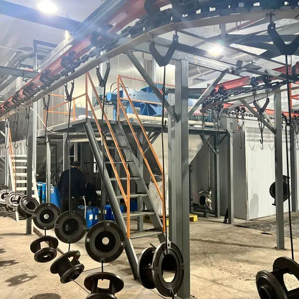
Overhead Conveyor Design
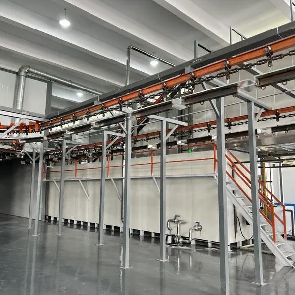
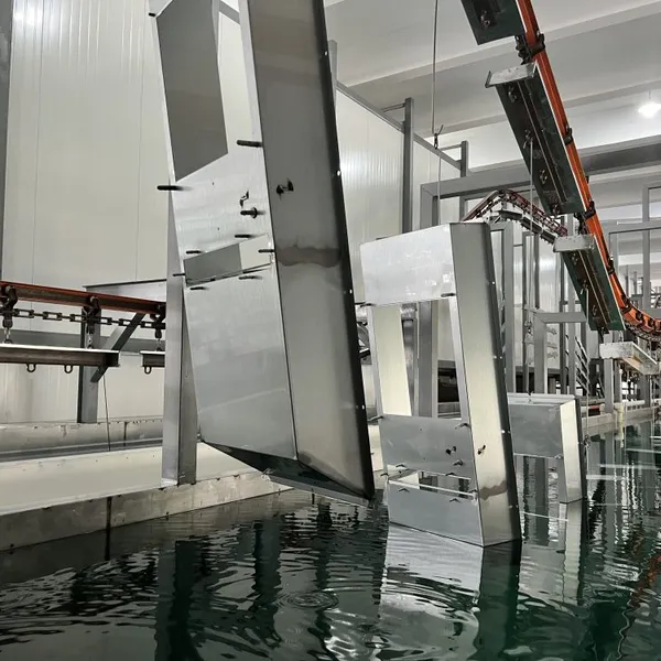
An overhead conveyor design suspends workpieces from hooks, jigs, or racks that hang below an elevated track. This approach keeps the factory floor clear for tanks, booths, and ovens, and it gives spray guns access to most part surfaces without complex fixturing.
Overhead designs work best for:
Small to medium metal parts such as brackets, hinges, appliance panels, and hardware
Powder coating lines where parts need 360-degree exposure
Factories with limited floor space but adequate ceiling height
Processes where operators load and unload at ergonomic heights
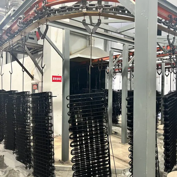
The track can run straight, curve around columns, or climb and descend to match ceiling profiles. Chain selection must account for pull load, pitch, and the corrosive atmosphere near pretreatment stages. Carriers must keep parts stable as they move through the spray pattern.
Deqing Leixin often integrates aerial conveying system layouts into powder coating lines for appliance, hardware, and furniture manufacturers. The elevated track routes above existing equipment and can pass through wall openings when the paint shop is divided into zones.
Ground Conveyor Design
A ground conveyor design moves parts on pallets, skids, or slats that ride on a floor-level chain. This configuration supports heavy, oversized, or top-heavy workpieces that are difficult or unsafe to hang.
Ground designs work best for:
Large electric cabinets, elevator panels, and assembled appliances
Heavy castings or weldments that exceed overhead load limits
Parts with complex bases that would swing on a hook
Lines where automated loading from upstream fabrication cells is required
The trade-off is floor space. A ground track needs clear pathways, guarding, and careful integration with booth and oven openings. It also limits access to the underside of the part unless the fixture elevates or rotates the workpiece.
Hybrid Conveyor Design
Some factories need both. A hybrid conveyor design might use an overhead chain for pretreatment and spray, then lower parts to a ground conveyor for curing and cooling. Hybrid layouts are more complex, but they solve problems that neither pure overhead nor pure ground designs can handle alone.
Adding Power-and-Free Buffer Zones
A standard overhead or ground conveyor moves every carrier at the same speed. That works when all parts share the same process time. It fails when mixed workpieces need different dwell times or when one station must pause for quality checks.
A power and free conveyor design separates the propulsion chain from the carrier track. The powered chain engages a carrier only when the controller wants it to move. Each carrier can stop, buffer, or divert without stopping the main chain.
This capability matters in three common scenarios:
Different cure times: Thick castings need longer oven dwell than thin sheet metal. A power-and-free section lets heavy carriers pause in the oven while lighter carriers continue through.
Quality hold points: Operators can pull a carrier offline for inspection without shutting down the line.
Loading imbalance: Buffer zones absorb uneven loading at the start of the shift so the rest of the line runs steadily.
The downside is higher mechanical complexity and cost. For high-mix, low-volume operations, however, the flexibility usually pays back through better equipment utilization and fewer changeover delays.
A power-and-free conveyor line design also requires more advanced controls. The controller must track each carrier, know its recipe, and release it at the right moment. That is where the Programmable Logic Controller (PLC) and Human-Machine Interface (HMI) become essential.
Conveyor Line Design Calculations: Speed, Spacing, and Length
Every conveyor line design rests on a few basic calculations. These numbers connect the workpiece data to the physical layout.
Line Speed
Line speed is usually expressed in meters per minute. It is derived from the slowest required process time and the length of that process zone. For example, if a curing oven is 30 meters long and parts need 20 minutes inside, the line speed must be:
Line speed = oven length ÷ cure time = 30 m ÷ 20 min = 1.5 m/min
This speed then governs every other stage. If the spray booth can only handle one part every 90 seconds, the carrier spacing must match that interval.
Carrier Spacing
Carrier spacing, or pitch, is the center-to-center distance between consecutive carriers. It is calculated from line speed and target output:
Carrier pitch = line speed × time between parts
If the line speed is 1.5 m/min and the target is one part every 60 seconds, the pitch becomes 1.5 meters. The carrier must be long enough to hold the part without collision, and the pitch must fit within the oven length without wasting capacity.
Total Track Length
The total track length equals the sum of all process zones plus loading, unloading, transfer, and return paths. A conveyor line design that ignores the return leg may look compact on paper but leave no room for empty carriers to cycle back to the load station.
Buffer Zones
Buffer zones add carriers that can queue before a constrained station. A good rule of thumb is to provide at least two to four empty carrier positions before the spray booth and curing oven. This prevents a brief loading delay from starving the downstream process.
Integrating Controls With the Conveyor System
The mechanical layout is only half of the conveyor line design. The other half is the control system that coordinates motion with process parameters.
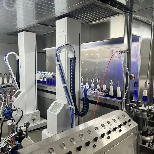
Most modern coating lines use a Programmable Logic Controller (PLC) as the central control device. The PLC receives inputs from sensors along the line, such as carrier proximity switches, oven temperature transmitters, and spray booth pressure sensors. It sends outputs to variable-frequency drives, reciprocator servo motors, oven burners, and conveyor drive units.
The operator interface is typically a Human-Machine Interface (HMI) touch screen mounted at the line control panel. From the HMI, operators can select recipes for different workpieces, adjust conveyor speed within safe limits, view alarms, and monitor production counts. Advanced systems may also include a large-screen production display for supervisors and optional remote monitoring for off-site technical support.
A well-designed control layer for a conveyor system for coating line operations should deliver these functions:
Speed synchronization between pretreatment, spray, and curing stages
Carrier tracking so the controller knows which part is at which station
Automatic buffering to absorb short stops without shutting down the entire line
Safety interlocks that prevent spray operation if a carrier is missing or misaligned
Recipe management that loads the correct parameters for each workpiece type
Deqing Leixin's PLC control system options include touch-screen HMI operation, recipe storage, and optional remote large-screen displays. Integrating these controls with the mechanical conveyor turns transport equipment into a synchronized production system.
Common Mistakes When Designing the Conveyor
Even experienced buyers can make costly errors when planning a conveyor line design. Here are the most common pitfalls.
Undersizing the conveyor for peak load leads to stretched chains, premature wear, and alignment drift. Always design for the maximum workpiece weight plus a safety margin, not the average load.
Ignoring the thermal environment causes bearing failures and lubricant breakdown near curing ovens. Specify heat-resistant components and shielded bearings where oven radiation is present.
Specifying fixed speed when variable speed is needed limits the line's ability to handle different products or adjust for seasonal temperature variations. A variable-frequency drive is almost always worth the incremental cost.
Neglecting carrier tracking makes it impossible to trace quality issues back to specific stations. Even basic carrier identification improves troubleshooting and reduces response time when defects appear.
Treating controls as an afterthought creates integration problems later. The PLC, HMI, sensors, and drives should be designed together, not patched on after the mechanical system is installed.
Avoiding these mistakes requires close collaboration between the coating line supplier, the controls engineer, and the customer's operations team. Deqing Leixin provides factory layout assessment, control system integration, and operator training as part of its turnkey project approach.
Conveyor Line Design FAQ
What is conveyor line design?
Conveyor line design is the process of selecting the transport system, carrier spacing, line speed, and control architecture that moves workpieces through a coating line. It covers the track layout, buffer zones, and integration with pretreatment, spray, and curing equipment.
Why does conveyor line design matter for finish quality?
The conveyor line design sets the dwell time in each process stage. If parts move too quickly through the curing oven, the coating under-cures. If they bunch up in the spray booth, film thickness becomes uneven. Good design keeps every stage in sync.
How do you calculate speed for a conveyor line design?
Divide the length of the longest process zone by the required dwell time. For example, a 30-meter oven that needs 20 minutes of cure time gives a line speed of 1.5 meters per minute. The rest of the conveyor line design is then built around that speed.
When should a conveyor line design include power-and-free buffering?
Use power-and-free buffering when the line handles mixed workpieces with different process times, or when you need quality hold points without stopping the main chain. It adds cost but prevents the whole conveyor line design from being limited by the slowest part.
What workpiece data is needed for a conveyor line design?
You need the largest part dimensions and weight, daily output target, required process times, available factory space, and preferred heating source. These inputs determine the chain size, carrier pitch, total track length, and control requirements for the conveyor line design.
Conclusion: Build Your Coating Line Around a Sound Conveyor Design
A strong conveyor line design is more than a way to move parts from one station to the next. In a modern coating line, it is the coordination layer that keeps pretreatment, spray application, curing, and cooling in time with one another. When the conveyor is properly sized, buffered, and controlled, quality becomes more consistent, throughput rises, and labor costs fall.
Think of the coating line conveyor as the production heartbeat. If it is too slow, the spray booth and curing oven wait. If it is too fast, parts leave the oven before they reach the required metal temperature.
Deqing Leixin follows ISO 9001:2015 quality management practices through design, manufacturing, installation, and commissioning so that every line is documented, repeatable, and traceable.
Key takeaways from this guide:
Start the conveyor line design with accurate workpiece dimensions, weights, and daily output targets.
Choose overhead, ground, or hybrid layouts based on part access, floor space, and load limits.
Use power-and-free sections when high-mix production requires different process times or buffer zones.
Calculate line speed, carrier spacing, and total track length from the slowest required process stage.
Integrate PLC, HMI, and sensor systems early; controls should be designed with the mechanics, not after them.
Design for peak load and thermal exposure to avoid premature wear and unplanned downtime.
If you are evaluating a new coating line or planning an upgrade, start the conversation with your workpiece specifications and production targets. A conveyor line design built around real process requirements will serve your operation far better than one added as an afterthought.
Ready to engineer a conveyor line design around your production goals? Request a free line design drawing or contact our engineering team to discuss your workpiece dimensions, throughput targets, and factory layout.
Recently Posted
-
Conveyor Speed Calculation for Coating Lines: A Complete Guide
June 26, 2026Last March, a hardware manufacturer in Ningbo raised the chain speed on its powder coating line by 15% to clear a backlog. Three d Read More
 -
Overhead Conveyor System: Engineering Guide for Coating Lines
June 26, 2026Last autumn, a hardware manufacturer in Ningbo faced a familiar problem. Their new powder coating line had to fit inside a buildin Read More
 -
Industrial Paint Booth: A Complete Engineering Guide for Manufacturers
June 26, 2026When Mike Chen expanded his metal furniture factory in Zhejiang Province last spring, he assumed the new spray area would solve hi Read More
 -
Paint Curing Process: An Engineer's Guide to Industrial Oven Curing
June 25, 2026The most expensive mistake in a coating line isn't always a misaligned spray gun or the wrong powder. It's a curing oven t Read More

Contact Us
Recommended Products
-
 Industrial Custom Spray Coating Line for Hardware Anti‑Corrosion TreatmentNegotiableMOQ: 1 Set
 -
Industrial Electrophoresis Line for Metal Water Pump Workpieces ProcessingNegotiableMOQ: 1 Set
-
Custom E‑Coating Production Line for Water Pump Parts Surface FinishingNegotiableMOQ: 1 Set
-
China OEM Custom E-Coating Machine and Cathodic Electrophoresis Production LineNegotiableMOQ: 1 Set
-
Industrial Electrophoretic Coating Line With Custom Design for Metal WorkpiecesNegotiableMOQ: 1 Set
-
Intelligent Automated Electrophoretic Coating Line for Powder Coating Production EquipmentNegotiableMOQ: 1 Set
-
Full Automatic Custom Electrophoretic Coating Line for Industrial Metal ComponentsNegotiableMOQ: 1 Set
-
Heavy‑Duty Continuous Powder Coating Line for Big Cabinet Anti‑Corrosion FinishingNegotiableMOQ: 1 Set
-
Energy‑Saving Powder Coating Line for Large Industrial Cabinet Surface ProtectionNegotiableMOQ: 1 Set
-
Environmental Friendly Powder Coating Line With High Recovery for Large CabinetsNegotiableMOQ: 1 Set
-
Large Manual Industrial Curing Oven for Metal Powder Coating MachineryNegotiableMOQ: 1 Set
-
Industrial Plastic Drying Oven With PLC Control and 304 Stainless Steel HopperNegotiableMOQ: 1 Set
-
High Efficiency Plastic Raw Material Dryer for Plastic ProcessingNegotiableMOQ: 1 Set
-
Compact E-Coating System for Small Metal Components in Automotive & Medical Device ProductionNegotiableMOQ: 1 Piece
-
Gantry Transport Type Electrophoretic Coating Line for Industrial WorkpiecesNegotiableMOQ: 1 Set
-
Custom Gantry Electrophoretic Coating Line for Automotive Component FinishingNegotiableMOQ: 1 Set
-
Large Workpiece Stainless Steel Manual Powder Spray Booth With Ventilation SystemNegotiableMOQ: 1 Set
-
Large Capacity Stainless Steel Manual Powder Spray Booth With Powder Recovery SystemNegotiableMOQ: 1 Set
-
Automatic Large Workpiece Powder Spray Booth for Metal FabricationNegotiableMOQ: 1 Set
-
Powder Spraying Room With Stainless Steel Frame and PLC ControlNegotiableMOQ: 1 Set